Understanding ONA in Satellite Imagery: What is Off Nadir Angle and What Is It Used For?
- Zuzana Hajkova, Content Marketing Coordinator, EUSI
Off Nadir Angle (ONA) plays a crucial role in the quality of optical satellite imagery. It influences its resolution and clarity, decides the visibility of features, and makes it easier or harder to identify objects. Moreover, ONA is used to create stereo imagery and 3D models of the Earth’s surface. Read on to learn more.
What is ONA?
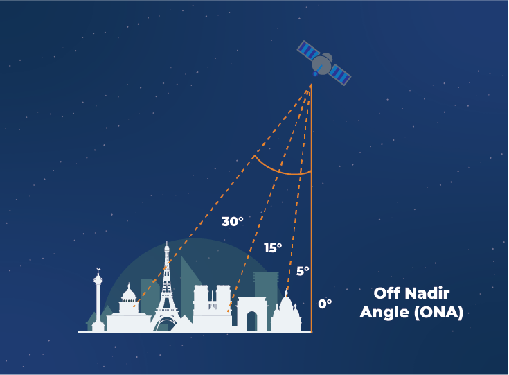
Off Nadir Angle (ONA) refers to the angle between the satellite’s nadir, which is directly below the satellite, and the point on the Earth’s surface which is being observed. That means that if a satellite is directly above the area of interest, the ONA will be 0°. The farther the satellite, the higher the ONA. This number influences the quality and characteristics of optical imagery collections.
The impact of ONA on the quality of satellite images
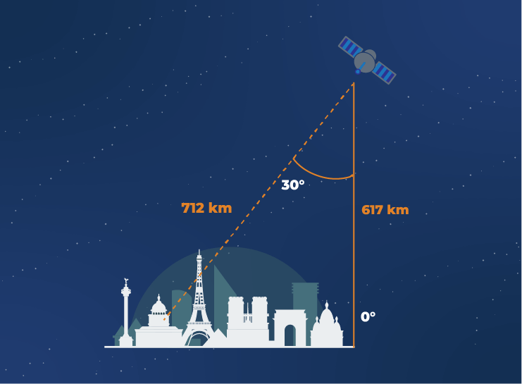
The Off Nadir Angle influences the clarity and sharpness of satellite imagery, and thus the interpretability of the data. For example the Maxar WorldView-3 satellite operates at 617 km altitude collecting images at up to 30 cm resolution (one pixel in the image represents a 30 x 30 cm spot on the ground). If the satellite collects an area of interest directly under it – at 0° ONA –, the sensor is pointing straight down and the satellite is as close to the target as possible, resulting in the best achievable resolution: 30 cm. On the other hand, if the satellite is further away and collects the target from a higher ONA, the distance between the satellite and the target is greater, leading to a lower resolution, slightly less clarity and more haze.
To sum up, images with a lower ONA have a higher resolution. If a satellite sensor collects at the resolution of 30–40 cm, an image with a 0° ONA will have a resolution of 30 cm, meanwhile an image with a 15° ONA will have a resolution about 35 cm and an image with a 30° ONA will be closer to 40 cm.
Does it mean that a lower Off Nadir Angle is better? Not necessarily.
Lower ONA isn’t always better
While lower ONA values typically result in sharper images with less distortion, they may not always be desirable. This has two reasons:
- Visibility of side features
- Collection opportunities
A satellite image collected from nadir (0° ONA) will show the place directly from above – for example, an image of an aircraft hangar will look just like a rectangle, making it harder to identify the object. On the contrary, with higher ONA, you can see features that are only visible from the side. You will see the hangar’s door, any signs and other features, as well as the characteristics of buildings, such as windows or wall materials.
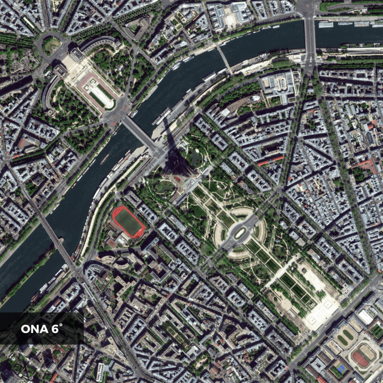
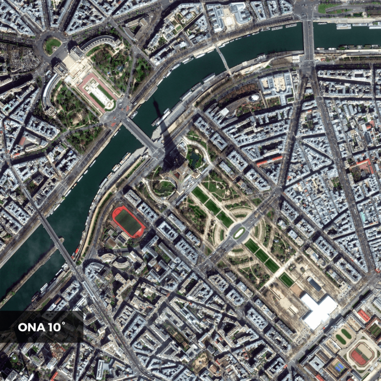
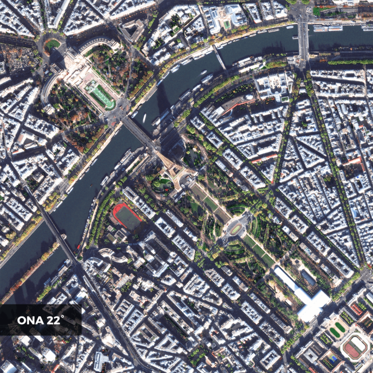
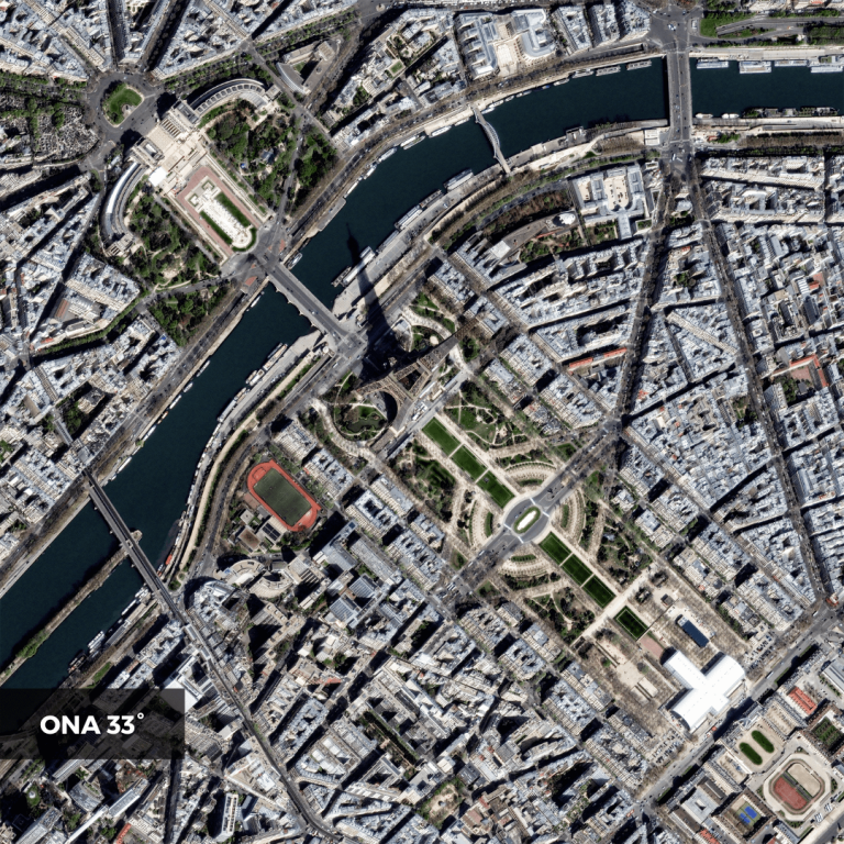
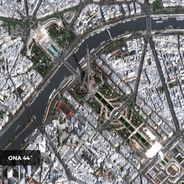
Moreover, a requirement for extremely low ONA values can limit the opportunities to collect the area, necessitating more passes to capture a larger region. That can be limiting especially in time-critical applications, such as Emergency Response, when it is crucial to obtain the image as quickly as possible – preferably within a single satellite pass. An immediately collected image with a higher ONA and a slightly lower resolution may be better than waiting for the satellite to pass directly above the area of interest.
What is the ideal ONA?
The ideal ONA varies based on the application. It always depends on the needs, requirements and goals of a specific remote sensing project. In general:
- For detailed mapping and analysis, a lower ONA is preferable to provide the best possible resolution and maximize data quality.
- For large-scale coverage or monitoring purposes, a slightly higher ONA may be better as it allows for more pass opportunities, and therefore a faster collection of the area.
- Last but not least, it depends on your need to see side features, such as signs or windows.
It’s essential to strike the balance between image quality, feature visibility, and satellite coverage based on the intended use.
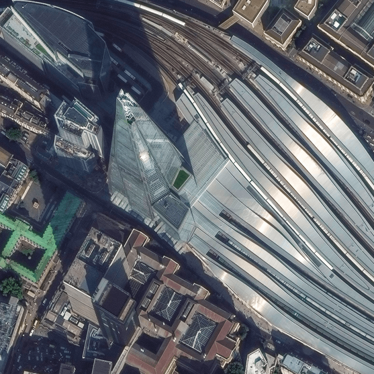
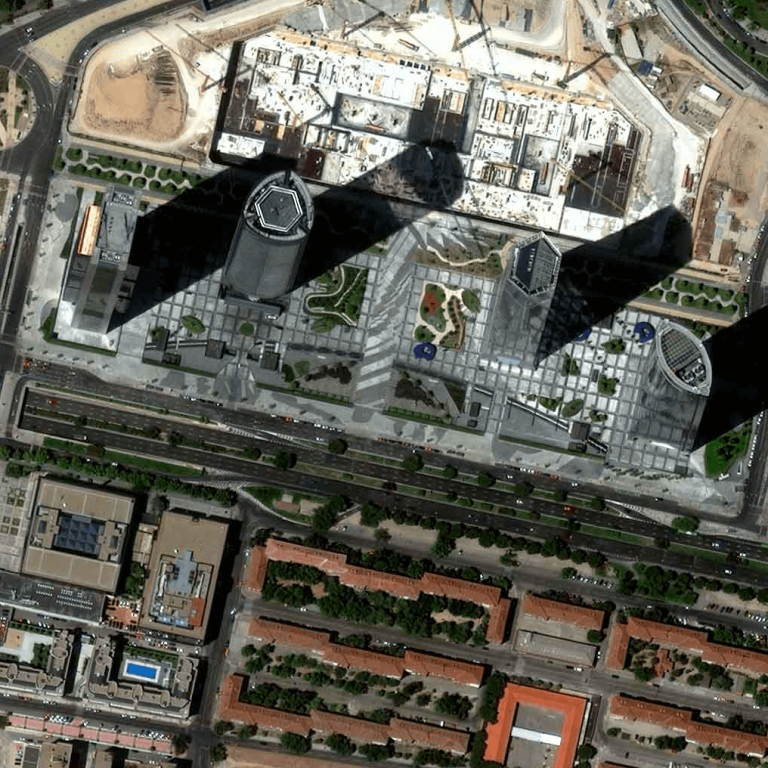
Imaging from a wrong angle may lead to sun glint destroying the image
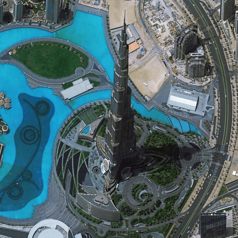
The ONA angle is crucial for eliminating sun glint in satellite images. Sun glint is the reflection of light in satellite or aerial imagery – it can look like a bright glare or blurry streaks of light, often obscuring the underlying features and making it challenging to extract useful information from the data. This phenomenon occurs when sunlight reflects off a surface, such as a metal roof or a body of water, at the same angle that the satellite sensor observes it. By adjusting the angle at which the satellite and its sensor image a target, it is possible to reduce or even completely avoid sun glint in satellite images. At EUSI, we do this by employing the Intelligent Collection Planning process.
But that’s not the only use of the ability to manually adjust ONA.
High ONA satellite imagery as art
Combining different ONAs for stereo imagery
Combining images captured at different Off Nadir Angles is used to produce stereo imagery. In this case, an area of interest is collected from two or more angles and delivered as a single set of data to give an incredibly accurate elevation dataset and minimise hidden features. If the target is captured from three angles, it’s called tri-stereo imagery – like in the animation below.
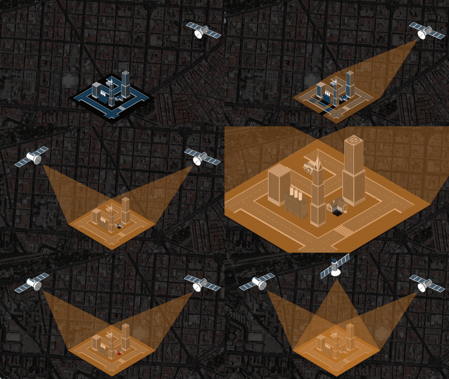
The resulting images are used to produce a Digital Elevation Model – DEM. The more images with different ONAs you can use to create the model, the more accurate the data is. At EUSI, we offer imaging from two (stereo), three (tri-stereo), or even five angles (multi-stereo).

Nicole Enghuber
Earth Observation Support Specialist at EUSI
We are mapping European cities in 3D
“Together with GAF AG, we have introduced the initiative to map all major European metro areas in 3D on a yearly basis. For this initiative, called UrbanPix3D, we provide tri-stereo imagery at 30 cm resolution. We use these Off Nadir Angles:
- One image at 0–10° ONA
- Two images at 12,5 – 15° ONA
To see an example, watch a flight over a Digital Elevation Model of Berlin created by GAF from EUSI’s satellite imagery.”
Three types of Digital Elevation Models
DEMs created from (tri-)stereo imagery can be generalised into 3 product categories:
- Digital Terrain Models
- Digital Surface Models
- 3D Visualization Models
A Digital Terrain Model (DTM) might have different definitions depending on the region. But in general, it is a bare-earth model. Anything above the surface, such as vegetation or structures, will not be included. Common applications of DTM include hydrology and mapping for mining or construction projects.
A Digital Surface Model (DSM) includes not only the bare earth, but also every bit of vegetation and built structures. DSM provide an extremely accurate representation of the world as it actually is. They are useful for telecom infrastructure, urban planning and vegetation management.
A 3D Visualisation Model is a mesh data format that can be integrated into simulators or be used for visualisation. 3D Models are extensively used for military mission planning, flight simulators, video game development and visual effects for the film industry.
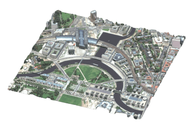
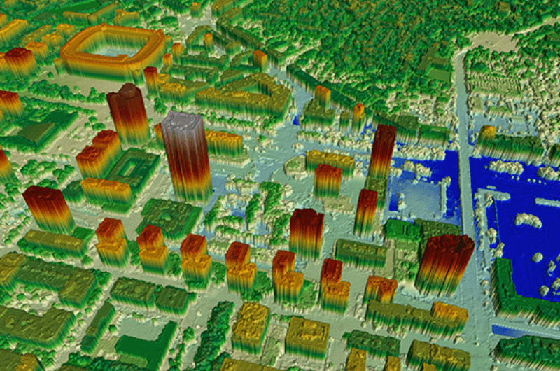
With the rise of digitalization, new solutions like stereo imagery and elevation models are increasingly disrupting industries and propelling businesses to greater heights. The highest resolution of Digital Elevation Models currently available is 30 cm, and the industry offers an array of different solutions to choose from.
Key takeaways
- Off Nadir Angle (ONA) is the angle between the satellite’s nadir, which is directly below the satellite, and the point on the Earth’s surface which is being observed.
- Lower ONA leads to higher resolution but at the same time limits the visibility of side features and decreases satellite pass opportunities.
- The ideal ONA always depends on the specific goals of a remote sensing project.
- By adjusting the viewing angle of the satellite, you can eliminate sun glint.
- Combining images collected at different ONAs is used to produce stereo imagery. The more angles you use, the higher the quality is.
- Stereo imagery is used to produce Digital Elevation Models. We can divide them into three categories: Digital Terrain Models, Digital Surface Models, and 3D Visualisation Models.
Related Stories

GEOSeries: Extracting Insights From High Resolution SAR Imagery for Time-Sensitive Analysis
In this webinar, industry experts and advanced users of Umbra SAR data showcase how they transform SAR imagery into actionable insights in real-world mapping, monitoring and intelligence applications. See how NV5 and Umbra leverage ENVI SAR Essentials for advanced processing with time-efficient results, converting analytics into valuable intelligence.
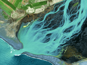
Using Satellite Imagery to Build Water Resilience Across Europe
Water across Europe is facing severe pressure. Climate change, urbanisation, agricultural demands and other sources of pollution are threatening water security and creating critical challenges that need to be addressed. We have to act quickly, build stronger systems and create sustainable water resilience practices – so that both natural ecosystems and human communities can thrive. Here is how satellite imagery from EUSI can help.
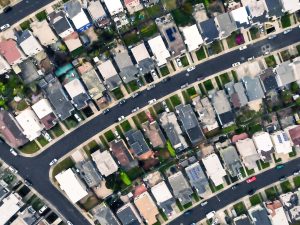
EUSI and Albedo Partner to Deliver 10 cm Resolution Satellite Imagery to Europe
It is our pleasure to announce the partnership with Albedo, a builder of high-performance spacecraft and the first satellite designed to operate commercially in VLEO (Very Low Earth Orbit). This partnership will bring the world’s highest resolution satellite imagery to the European and North African market.
Updating the Land Parcel Identification Systems in 2025: The Benefits of Using Satellite Images
Agricultural paying agencies across Europe face increasing challenges in maintaining accurate and up-to-date Land Parcel Identification Systems (LPIS), ensuring compliance with the Common Agricultural Policy (CAP) and supporting sustainable agricultural practices.


